Connections Macro
Most of the icons in ProtaSteel such as connections, purlins, sag rods & girts are called “macros”. A macro is generally defined as a shortcut tool that specifies how a certain input sequence will result in a desired output according to a defined procedure. The instruction on how to use each macro is shown in the tooltip if you hover the mouse cursor over the icon.
- Before creating the element using the macro, you can setup the macro settings, e.g. member profile, plate offsets, bolts, etc. by right-clicking on the macro icon which will bring up the Macro dialog. (refer to the GIF below)
- Once a macro is clicked, the mouse cursor will change to the hand icon
 meaning that it is waiting for object(s) selection or crosshair + meaning it is waiting for point selection. Perform the required action(s) to get the desired result, as shown in the tooltip.
 - The macro will remain activated; you can continue use the macro without having to click on the macro icon again.
- Once you have finished, you must press ESC to cancel & stop the macro. The mouse cursor will change back to default arrow (selection mode).
- After creating the elements in a group such as the purlins, each element will have its individual properties; which can be changed by double-clicking on it > this will bring up the Element dialog.
- However, all the elements are still associated with the macro & can be changed in a group.
This can be done by selecting the macro sign& then press ENTER or Double-Click will bring up the macro dialog. After making the changes, clicking Apply will apply to all the elements associated with the macro. Clicking "Set as Default" will reset the properties of the macro to default settings for the entire project.
Select Macro Sign which Associated with Elements /Components
- Macro sign can be easily selected on screen, however, it is more difficult to distinguish macro sign when the number of objects in the model increases. In such situation, users are advised to follow steps below to select the macro sign:
- Select any element or component of the macro (e.g. a plate of a connection)
- then press “M” will turn the macro sign into red color which means the macro sign is selected.
- followed by ENTER which will expose the Macro dialog.
- You can also delete the all the elements & components of a macro by selecting the macro sign & then press DELETE.
- It is highly recommended you review settings of the macro before executing it.
Select Macro Connection
To select all elements/components which related to the macro sign, user need to:
- Select all or the macro sign or any elements/components
- Press CTRL + M to select all macro associated elements/components
Commands in Macros Tab
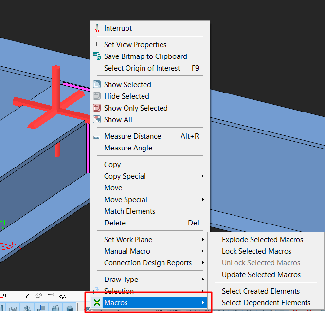
Commands in Macros tab can be accessed by right clicking on any Macro Sign. Commands in Macros Tab are:

- Explode Selected Macros: breaks a compound object into its components object.
- Lock/Unlock Selected Macros: Locking a macro means that the changes being made on the elements will not be reflected on macro which the elements depend on it. Likewise, unlocking a macro allows the changes being made on the elements will be reflected on the macro.
- Update Selected Macros: Macros will not be automatically updated according to the changes made in Project Preferences. Users need to manually click "Update Selected Macros" to update the macro.
- Select Created Elements: This command will select the elements which created the selected macro sign
- Select Dependent Elements: This command will select the elements which depends on the selected macro sign.
Working Principle of Connection Macros
Elements/ Components associated with Macros can be classified into 3 groups:
- Elements/Components that the macro is depending on (Structural elements such as column, beam, cross, purlin, belt, etc.): When the changes are made on elements/ components (e.g. beam section increased, column height increased, etc), the macro will be redesigned itself based on the newly defined elements/ components.
- Elements created by macro (elements such as bolts, plates, welds, etc.): The macro will not be redesigned if any elements/components created by Macro are changed.
GIF above shows that the macro will not redesign although bolt diameter and plate thickness are changed. - Element Macro (such as anchor bolt): One of the elements created by element macro is deleted, the whole macro will be deleted as well. GIF below shows that deleting washer in anchor bolt, the whole macro will be deleted.

- The connection consists of plates, bolts & welds. Each element has its individual properties and can be selected, deleted or changed. Double-clicking it will reveal the element properties.
- The entire macro connection is represented by the macro sign
. Double-clicking on it will bring out the Macro dialog box where the entire connection can be changed.
- It is highly recommended you review settings of the connection macro before executing it.
Related Articles
Steel Connection Scope and Assumptions
Once we have finalized position of the steel members, we can start “connecting” the steel members, i.e. create connections. Connection can be created in two ways: Automatically using the connection macros from Macro Gallery or IntelliConnect Manually ...Steel Design & Composite Member Settings
Steel design & composite member setting is important to preset before starting to design any steel or composite steel members. By presetting these design parameters can save a significant amount of time for user compare to user who set after ...Composite Beam Design General Principles
ProtaStructure supports a powerful composite slab/beam design. The overview of the composite slab modeling, analysis, and design is as follows: 1. Metal decks can be chosen from a Metal Deck Library. 2. Shear studs can be specified from a Stud ...Structural Modelling Overview
Techniques for member creation and loading are described in this section. Also described here are those other modelling related functions contained on the “Member” pulldown. Additional modelling related topics can be found in the preceding Graphic ...Column and Wall Design Contents
The "Column Section Design" form can be accessed by clicking the “Column Section Design” option under the “Design” pulldown menu in the Graphic Editor. ProtaStructure can design rectangular, circular and polyline columns under uniaxial or biaxial ...