Working with Slab Strips
Usage of Slab Strips
Slab Strips are used for creating a means for the analysis, design and curtailment of slabs. Slabs along the strip are determined and their analysis is performed along the strip if the moment coefficients method is selected. Similarly, a continuous beam analysis is performed along the strips if ribbed slabs are encountered.
If the method of analysis is selected to be finite elements, then the design results along the strips are collected from the analysis results based on the type of slab strip set by the user.
The Usage of Slab Strips:
- Analysis and Design of Slabs: Slabs and Ribbed Slabs that are found along the strips are analysed and designed. If the strip is a Finite Element Strip, then the analysis results are collected from the finite element model results otherwise, the analysis of the slabs along the strip is carried out using the moment coefficient method.
- Insertion of the Reinforcement Bars: Steel bars calculated during the analysis of the slabs are inserted along the strip based on the Strip Type parameter.
- Analysis and Design of Ribbed Slabs: A continuous beam model is created along the strip for the analysis and design of ribs.
Steel Bars are calculated only along the direction of the slab strips. For that reason, strips must be defined along both directions for two-way slabs. More than one strip may need to be defined along one direction for L-shape slabs to take into account different spans.
Similarly, more than one strip may need to be defined along slabs with different adjacent slabs along an edge. In such cases, in order to make a correct quantity extraction, slab span lines may need to be manually modified.

For a detailed explanation of the usage of slab strips, you can refer to Slab Analysis and Design Overview.
For more detailed explanation of each different type of Finite Element FE Strip, please refer to Finite Element FE Strip.
Slab Strip Properties
Slab Strip Label
- Dir : To assign the direction of the slab strip. Select "X" if it is horizontal, select "Y" if it is vertical.
- No. : To assign the number of the slab strip. "99" is the largest number that can be assigned.
- Rebar. Row (Manual Strip / FE-Strip - Fixed Band) : To assign rebar layer (ie. 1 or 2). Main slab reinf. can be assigned as "1" and distribution rebar can be assigned as "2".
- For the 1st layer steel : Cover to Bar Center = Concrete Cover + (Bar Size Along Strip / 2)
- For the 2nd layer steel : Cover to Bar Center = Concrete Cover + (Bar Size Along Strip / 2) + (Bar Size Along the Other Direction
In slab systems with beams, steel layers will automatically be set using the plan dimensions of the slabs that the strip intersects.
For example, the steel bars that are located along the short span of the slab will have the layer number “1 ” whereas the bars in the other direction are located in Steel Layer “2 ”.
Strip Type
- Type : There are 3 different strip types in ProtaStructure which are:
- Analytical Strip : Design slab rebars based on Building Analysis result (Moment Coefficient Method) without FE Floor Analysis or Building Analysis Floor meshing.
These strips must pass through the slabs supported by beams and walls. Building Analysis must be performed. Refer : Analytical Strip (Moment Coefficient Method) - FE Strip : Design slab rebars based on FE Floor Analysis or Building Analysis Floor meshing.
Building Analysis (with FE Floor/Foundation Analysis or Building Analysis FE Mesh) must be performed. Refer : Finite Element FE Strip
Only FE Strip type can select either to be " Span Strip" or "Fixed Band Strip".

Type of the Finite Element Strip must be consistent with the slab system.
For example, if you are working with a slab system with beams, the Finite Element Strip type must be “Span Strip”.
For example, if you are working with a slab system with beams, the Finite Element Strip type must be “Span Strip”.
Similarly, if the system you are working on is a flat plate, then differing with the location, “Fixed Band Strip” must be selected.
- Manual Strip : Manually assign slab rebars without analysis and design.Extra tab "St. Bars" can be found to fill in and display the steel bars associated with this strip.

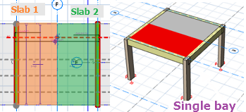
When applying Analytical Strip and FE strip - (Span Strip), avoid drawing across a single floor bay that has multiple slabs in it because the slab strips will always design only for the first slab it went across.
Single floor bay defined as a slab area between 2 beams/walls parallel to each other as a support for the slabs.
Single floor bay defined as a slab area between 2 beams/walls parallel to each other as a support for the slabs.
Analysis Results Source (FE Strip)
This option is visible and selectable only when "FE Strip" type is selected. Slab rebars design can either based on:
- Building Analysis FE mesh result, or
- FE Floor/Foundation Analysis result
Boundary Conditions (Analytical Strip / FE Strip-Span Strip)
Boundary condition only activates when Analytical strip or FE Strip (Span Strip) is selected.
In this section, slab start and end condition can be defined based on the icon.
Start of the strip will always be at the left (horizontally) or bottom (vertical), while the other point will be the end of the strip.
Slab Width (Boundary Conditions : Continuous)
"Slab width" is to defined the extension of rebars at the start or end of the strip when "Continuous" boundary condition is selected.
 An easy way of determining this dimension is clicking to this input field with the mouse and then selecting the slab (by clicking to the label in the plan window). Then the width along the strip will appear. The top steel bars are extended further into the adjacent slab by the anchorage length set by the user.
Scope Width (FE Strip-Fixed Band Strip)
"Scope Width" is the analysis width to be considered when acquire the slab analysis result (i.e. moment) to design the rebars when FE Strip (Fixed Band Strip) is selected.
The width for either side should never set to "0" to avoid analysis error.
To easily define the scope width, the ">" button can be used to auto calculate the width of each side by clicking on to the point where you wish to extent the strip width within the slab.
- Intergral Strip : To calculate the design moments using integral approach (average out the moment within the strip width), otherwise the maximum moments within the strip range will be used for rebars design.
- By default, the maximum peak nodal moment will be used for finite element slab design, e.g. column center line (as shown above)
- Integral option will average the design moment across the width of the strip
- The wider the strip, the lower the “averaged” design value, esp. at support region where the moment changes rapidly
- User should carefully evaluate how wide to create each strip when integral is chosen
Defining a New Slab Strip
Before inserting a Slab Strip:
- Beams and columns/walls along the strip must be defined, (except for FE Strip - Fixed Band Strip)
- Slabs or ribbed slabs along the strip must be inserted.
To define a new Slab Strip:
- Press the “Slab Strip” button located in the "Modelling" tab.
- "Slab Strip Properties” can be accessed by pressing on the “Slab Strip” button.
- Set the label of the slab strip to be defined. When automatic labelling is on, the strip labels will be assigned incrementally when a new strip is defined.
- If you are inserting a Finite Element Strip, then select the "Finite Element Strip " option in the Slab Strip Type.
- Draw new slab strip across the slab(s) that you wish to design using 2 insertion points. If moment coefficients are used, then the analysis of the strip will be performed immediately (if only Building Analysis is performed) and the selected reinforcement will be inserted.
- While for the Finite Element Strip, please run either the FE Floor Analysis or Building Analysis with FE Mesh (in Model options > Slab Model). From ProtaStructure 2022 onwards, FE Floor Analysis result will automatically transferred into the slab strip design.
- As long as the Building Analysis with/without FE mesh and/or FE Floor Analysis (if required for FE analysis source) is/are still valid, slab strip can be drawn without rerunning the Building Analysis/FE Floor Analysis.
- Perform the slab rebars design by going to "Design" tab > Slab Analysis and Design > "Slab Strip Design (Batch Mode)" or design individually. "Ribbed Slab Analysis" for ribbed slab.
For ribbed slab design procedure, please refer to Ribbed Slab Modelling & Design Procedure.
Editing an Existing Slab Strip
When a beam or slab along the strip is modified, the strips along these members must be edited. In order to edit an existing strip:
- Select the existing slab strip.
- Right-click and select “Properties”. (“Properties” can be accessed alternatively by pressing the “Slab Strip” button).
- Modify the fields such as "Label" or end conditions in the "Slab Strip Properties" form.
- Press the "Update" button in the form.
You can repeat this process to as many members as you wish. Only one member at a time can be edited by using this method.
Slab Strip Shortcut Menu
You can access the most often used command options for the Slab Strips in the shortcut menu (displayed by right-clicking the mouse) after selecting a Slab Strip.
A shortcut menu for a single Slab Strip selection includes “Slab Strip Check Design” and “Delete Steel Bars” options specific to a Slab Strip member. These option will be omitted from the shortcut menu when multiple Slab Strips are selected.
- Slab Strip Design : To access the “Slab Analysis and Design”.
- Update Steel Bars : To recalculate the slab steel bars design.
- Delete Steel Bars : To delete any exists steel bars assigned to the selected Slab Strip.
- Strip Profile : To show the force diagrams of the slab strip based on every load case/combination.
Related Articles
Working with Flat Slabs
Flat Slab Guidelines The modelling, analysis and design of flat slab is described in detail here : For ProtaStructure 2022 & later versions : Flat Slab Modelling, Analysis and Design For Flat Slab and Raft Design with Slab Patch Panel: Flat Slab and ...Slab Analysis, Design and Reports in ProtaStructure
Inserting slabs, analyzing and designing them are easy processes with ProtaStructure. With ProtaStructure, you can quickly manage the materials of the slabs, how the slabs will be graphically displayed, the building analysis and review of the ...Ribbed Slab Modelling & Design Procedure
Similar to ordinary slab plates, Ribbed/Waffle slabs can be analyzed separately from building under G and Q, or with the building model under all combinations. Ribbed /Waffle slabs must be analyzed using FE Approach. Modelling Procedure: Insert ...Slab Analysis and Design Procedure
Solid Slabs and Flat Slabs can be analysed and designed in ProtaStructure. General Procedure 1. Before designing the slabs, review the Slab Design Settings. 2. Slab reinforcements can be drawn automatically using “ Slab Strips ” function the ...Working with Slabs
Defining a New Slab Before inserting a Slab member its reference axes should be defined. To define a new Slab member: Display the storey level in the drawing area which will contain the slab. Press the “Slab” button located in "Modelling" ribbon. ...