Beam Section Design - Rebar Tab
General
Beam Section Design allows user to access beam reinforcement data, beam report and etc.
To access Beam Section Design, user can either:
- Select a beam, then click on "Section Design"
under Beam tab, or
- Select a beam, right-click to access shortcut menu and click on "Section Design"
Beam Section Design consists of two tabs:
- "Beams” tab
- "Rebars” tab
Rebar Tab
By default, Rebar tab will be the main tab to be displayed when section design is opened.
In this tab, we have 2 sections:
1. Toolbars :
- Select Bars : Various reinforcement and curtailment patterns are available in ProtaStructure and can be selected using the given pulldown list. The default reinforcement pattern can be preset in the "Beam Design Setting" (Building Setout tab > Settings Center > Beam > Rebar Patterns)
For more explanation on Reinforcement Pattern setting, please refer to Beam Design Settings > Rebar Patterns.
 When "Select Bars" is clicked, the program will auto-design the beam. Any manual edited rebars quantity and size will be replaced.
- Diagrams : To access the detail design diagram of the beam.
- Detail Drawings : To preview the detail drawing of the beam(s) in the current axis without accessing to ProtaDetails. Technically the same as the detailed drawing that will be produced in ProtaDetails.
- Display Moment Values : To present Beam Interactive Design dialogue.
- Scaled/Not Scaled : When "Not Scaled" is selected means the beam illustration/sketch is not to scale, whereas "Scaled" means that the illustration/sketch of the beam will be drawn to scale.
- User can left click to switch. The horizontal scale may be modified using the up and down buttons next to the "Scaled/Not Scaled" button.
- Modification of the horizontal scale may be necessary when the resolution of your display is not sufficient, or when you want to see more (or less) beams in one screen.
- Previous Span/ Next Span : To move between beam span.
- Copy Bars / Paste Bars : To copy & paste all rebars from a single span beam to another span beam.
- When user use "Copy Bars", the program will automatically copy the entire rebars of the beam in single span (including links, support bars, span bars), then paste the entire bars of single span beam to another selected beam when "Paste Bars" is clicked.
- If there is existing rebars, it will be replaced by the copied rebars when pasted.
- Paste Bars to All : To paste the copied entire bars of single beam to all of the beams in the dialogue.
- Summary Report : To produce summary of the beam design in report form.
- Detailed Report : Detail report containing clause by clause check.
- Ok and Cancel : Ok to apply change, cancel to exit without preserving any changes made.
2. Reinforcement Data Editor : Fields that shows the steel bars selected after beams are designed. Detail will be discussed in section below.3. Beam Status : If beam fails, the reason will be shown here (Alternatively check in the batch beam design report).
Reinforcement Data Editor
In data editor, the result is dynamic which means when user edits rebars, the program will make changes on the calculations accordingly and immediately then provide instant feedback back onto the data editor. The provided reinforcement patterns system is tailored made to mitigate/eliminate the requirement of extra editing of the detail drawings.
This Editor consists of four sections:
- The schematic sketch of the beam
- Excess Steel Area
- Feedback Field
- Reinforcement Data Field

The values in these fields will be displayed in red when fails to satisfy/comply to the minimum requirements.
The schematic sketch of the beam
On the top of the form, the beams on the current axis are drawn schematically. The sketch shows the supports, beam labels, section dimensions, span lengths and required steel areas (at the top & bottom edge, at supports & span).

Red cross indicates that the beam design is section insufficient.
Excess Steel Areas
The “Extra As” values indicate the excess steel area provided by the supplied steel at the same location.
Feedback Field
Beam requirement checks and additional information can be found in this field:
- As-min (Top/Bot) : Minimum required steel area calculated based on the minimum steel percentages.
- B-Up Middle (Only With Bent-Up Pattern) : These fields display the possible width of the middle straight section of the bent-up bars.
If the reinforcement pattern used does not include the bent-up bars, these values will not be shown. - s-Bar-CL (Top/Bot) : Center-to-center distance between the bars is calculated by formula:
S-Bar-CL = (Beam width - 2 (link size + concrete covers) - Nos of longitudinal bar * longitudinal bar sizes) / (Nos of longitudinal bar - 1). - Defl. Check Results : Beam deflection checks.
- x-Sup. Links Fields : Links in the support regions are calculated automatically and the calculated widths of the support regions are displayed here only when link at mid span is different compare to support link.
Reinforcement Data Field
The steel bar fields are arranged according to the reinforcement pattern selected. Navigation between the steel bar fields can be made by simply clicking the mouse button or by arrow keys.
Although we have set default reinforcement pattern, user can still modify each steel bar manually.
The automatically selected bars can be modified using the up/down buttons located adjacent to the selected steel bar field.
If any modification is made, recalculation of the supplied bars will be dynamically performed and other related fields will be updated as well.
Reinforcement Data Field - Hotkey
To navigate the steel bar fields between each span beam, user can:
- Scroll and select using mouse wheel, or,
- use the “Previous/Next Span” command
To modify rebar size, quantity or spacing, you can use the up/down buttons located on either side of the steel bar field. Alternatively, you can use the following short-cut keys to modify the steel bars:
| F1 | Increase steel bar quantity |
| F2 | Decrease steel bar quantity |
| F3 | Increase steel bar size |
| F4 | Decrease steel bar size |
F5 | Increase steel bar spacing (Link only) |
F6 | Increase steel bar spacing (Link only) |
For example, to modify 2T16 to 4T14, user can press F1 twice and F4 once.
Reinforcement Data Field - Rebars Type
The available steel bar type in ProtaStructure are outlined below. All of the following bar type will not be visible in all reinforcement patterns. The necessary bar groups will be available depending on the selected reinforcement pattern. Reinforcement patterns can be selected using the “Select Bars” button.
- Hanger Bars : Hanger bars are used mainly with the bent-up bar patterns to provide links to be connected. These bars are used at the top layer in beams and in bottom layer in the foundation beams.
- The number of hanger bars is usually determined based on the width of the section.
- The hanger bars are usually lapped at mid-span when the selected quantity and size is the same as the neighboring spans.
Unlike the top and bottom straight bars, hanger bars are not extended to 0.25L of the adjacent span.
- The “Min. No. of Hanger Bars” and “Min. Hanger Bar diameter” in the “Settings and Parameters” dialog controls the minimum number of bars that can be placed in each span and the size of the bars.
- The “Steel Bar Cut Length” field in the “Settings and Parameters” dialog controls when the bars will be lapped. The bars are extended along the spans until the “Steel Bar Cut Length” value is reached.
- These bars are used in both the span and support regions of the beam to satisfy the required steel area.
- Top Bars : Top straight bars are placed at top layers of beams.
- They are used in beam mid span to satisfy the required steel area.
- When extended to 0.25L / Lap to the adjacent beams, they are also used to satisfy the required steel area of the beam supports.
- The top bars will not be extended to the adjacent support when the top levels of the beams are not the same; therefore they will not be used to satisfy the required steel area of the supports of the adjacent span beam.
- In the first and last supports or when there is a level difference between the beams, these bars are extended to the column and a bob (bent of bars) is made when necessary to provide sufficient anchorage.
These bars can be used as hanger bars when it is desired that separate bars be put in every span.
- Support Top Bars : Support top bars are placed at top layers at supports of beams.
- They are used in support regions of both beams and are extended to satisfy the required steel areas.
- They are either extended to 0.25L to into the adjacent beams or lap with the span bars.
- In the first and last supports or when there is a level difference between the beams, these bars are extended to the column and a bob is made when necessary to provide sufficient anchorage.
- Two different groups of support top bars will be provided when the top levels of the beams are not the same.
- Bent-up Bars : Bent-up bars will be available when a reinforcement pattern that uses this bar group is selected. Bent-up bars are used in top layers of support regions and bottom layer span regions.
- They are extended to 0.25L to the adjacent beams.
- Therefore they are used to satisfy the required steel area of the supports of the adjacent span beams.
- Bent-up bar curtailment style is controlled by the parameters provided in the “Bent-up Bar Controls” section of the “Settings and Parameters” menu.
- Bottom Bars : Bottom straight bars are placed at the bottom layers of the beams.
- They are used in both the span and support regions of the beam to satisfy the required steel area.
- When extended to 0.25L / Lap to the adjacent beams, they are also used to satisfy the required steel area of the supports of the adjacent beams.
- The bottom bars will not be extended to the adjacent support when the bottom levels of the beams are not the same. Therefore they will not be used to satisfy the required steel area of the supports of that adjacent beam.
- In the first and last supports or when there is a level difference between the beams, these bars are extended to the column and a bob is made when necessary to provide sufficient anchorage.
- Support Bottom Bars : Support bottom bars are placed at the bottom layers at the supports of beams.
- They are used in support regions of both beams and are extended to satisfy the required steel areas.
- They are either extended to 0.25L to into the adjacent beams or lap with the span bars.
- In the first and last supports or when there is a level difference between the beams, these bars are extended to the column and a bob is made when necessary to provide sufficient anchorage.
- Two different groups of support top bars will be provided when the bottom levels of the beams are not the same.
- Web Bars : Known as "Side Bars". For deeper beams bars are used in side faces of beams for control cracking.
- The number and spacing of these bars is determined based on the requirements of the selected codes of practice.
- The minimum bar size is determined based on the value specified in “Web Steel Diameter” field in the “Settings and Parameters” dialog.
- Links : Equally spaced links can be placed along the beams in three regions, namely, left and right supports and span.
- The width of the support regions is determined and displayed in the “x-Sup.Links” line in the Feedback Field.
- Link arrangement and calculation parameters are available in the “Links” page of the “Settings and Parameters” menu. Using these options, minimum and maximum link spacing, link diameter range and support links arrangement can be controlled.
Bent-up bars (if available) are not considered in shear design.Whenever the torsion force has exceeded the concrete torsional capacity of the beam (without rebar), torsion links (closed links) are automatically designed. The prefix 'T' will be shown beside the link type in ProtaDetails as shown in the diagram below: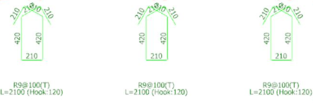
Edit Beam Size for Quick Check
You are able to directly change the beam size in design dialog. Below snapshot illustrates the required steps.
- Click and key-in the value and press "Enter"
- Click on "Select Bars" to quick check the beam design.
- Click "OK" to agree the changes that are made.
- Click "Cancel" to discard the changes.

Changing the beam size in this interface will invalidate Building Analysis results as weight & stiffness of structure has changed. Hence, you should re-run Building Analysis to obtain updated design forces. Then re-check the design of this beam to truly ensure it passes with the latest design forces.
Related Articles
Beam Section Design - Beam Tab
General Beam Section Design allows user to access beam reinforcement data, beam report and etc. To access Beam Section Design, user can either: Select a beam, then click on "Section Design" under Beam tab, or Select a beam, right click to access ...Beam Section Design Overview
Beam design will be discussed here. Before that, please take note that Building Analysis must always be performed and completed without error (some warnings that create in purpose and do not affect the result can be ignored) and building behaviour ...Beam Section Design Table - Design Tab
General Beam Section Design Table allows user to review or design all the beams in table. To access Beam Section Design Table, user can only go to Design tab > then click on "Storey Beams" . Beam Section Design Table consists of two tabs: "Design” ...Beam Section Design Table - Grouping Tab
General Beam Section Design Table allows user to review or design all the beams in table. To access Beam Section Design Table, user can only go to Design tab > then click on "Storey Beams" . Beam Section Design Table consists of two tabs: "Design” ...Beam Design to Eurocode
This design guide discusses the Beam Design to Eurocode 2 Design Code BS EN 1992-1-1:2004. Users who wish to understand the analysis and design calculation for storey beams, are recommended to read this document.