Using the options in the "Building Setout" tab > Storey Operations, storey information can be modified and an active storey can be selected. Alternatively, right-click on "storeys" in the Structure Tree can access the storey operation setting as well.
Select Storey
The Graphic Editor is organised to let the user work on one storey at a time. The active storey can be selected using the "Select Storey" option or directly double left-click on the label of the storey you want to make current. If you choose the “Select Storey” option, the selected storey will appear in the dialog and highlighted storey is the active storey.
Insert Storey
New storey can be inserted by:
- Right Click "Storey".
- Click "Insert Storey".
This tab is used to define or modify the number of storeys in the building.
Enter existing storey number in "Storey No." field will add a new storey above the storey. For example, in a 4 storeys building, entering 3 in "Storey No." input field will insert a new storey to the existing building and Storey 3 will be shifted up as Storey 4.
If the value input in "Storey No." field is more than the number of storey in the model, the newly added storeys will be inserted above the existing storeys. For example, for a 4 storeys building, entering 6 in "Storey No." input field, 2 new storeys will be added above the top floor.
When "Add Intermediate Storey" option is checked, then the height of selected storey will be sub-divided into 2 storeys.
For example, Storey 1 with 5 m height will be sub divided to 2 storeys with 2.5 m each storey.
Generate Storey
The information on a given storey can easily be copied to another storey using the "Generate Storey" menu option in the "Building" pulldown.
Note that a new storey cannot be added using this form. In order to increase the number of storeys in a building, use "Insert Storey".
The following fields will be available in this form:
Source Storey
Select a storey source to copy from the dropdown list of available storeys in the building.
Target Storey(s)
All the information defined in the "Source Storey" will be copied to the "Target Storey(s)".
During the copy operation, member labels will be generated to comply with the label conventions of the target storey. For example, when beam "1B20" is copied to the 3rd floor, the new beam will have the label "3B20".
Member Types to be Generated
You can use the member type filters to filter out the members that are not to be generated to the target storey.
All the information in a given storey can be deleted using the "Delete Storey Information".
Highlight the storey(s) from the table to be deleted and press "OK". All the defined objects in the selected storey(s) will be deleted.

Note that the number of storeys in the building cannot be decreased using this menu option. In order to decrease the number of storeys in a building, use "Remove Storey".
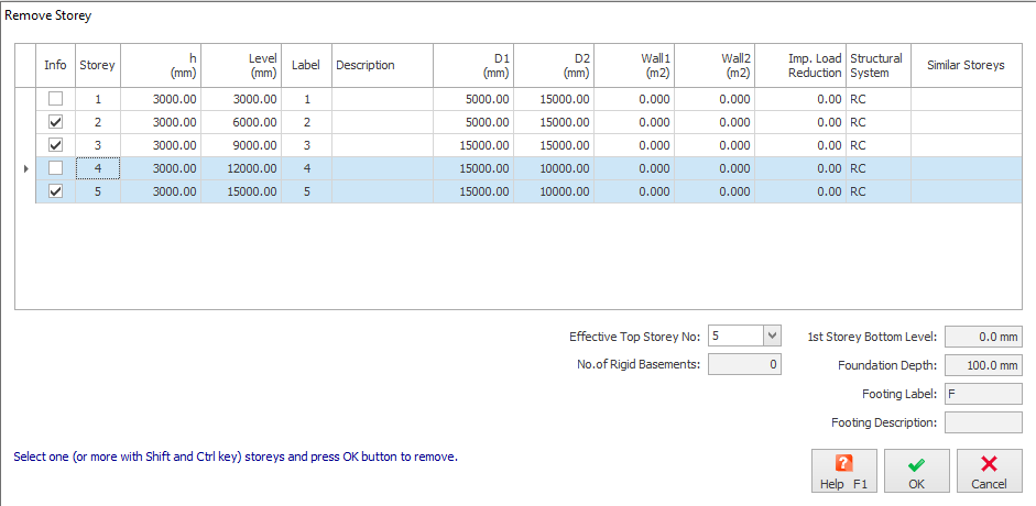
Remove Storey
One or more selected storey in the building can be removed using the "Remove Storey" menu option in the "Building" pulldown.
Highlight the storey(s) from the table that wish to be removed and press “OK” will remove the selected storey(s), the number of storeys in the building will be decreased accordingly.
Edit Storey
Use the "Edit Storey" to modify the parameters of a particular storey.
No. of Rigid Basements can be defined if the ground/soil level is higher than ST: 0. For example, if ST: 02 is the ground level, enter "2".

After setting No. of Rigid Basements, you have to re-apply Automatic Wind Load Calculation to make this setting effective.
Storey Height (h)
Storey height is defined as the distance between the top reference levels of the successive floors. Top reference level is by default top of slab and beams created in the corresponding storey.
Level
This is the storey top reference level that is automatically calculated based on the Storey Height & 1st Storey Bottom Level input field at the bottom of the dialog. This field cannot be modified manually as it must be auto-calculated.
The reference levels information can be shown in the plan / layout & beam detailing drawings. It does not affect the analysis at all.
1st Storey Bottom Level
As explained above, reference levels of the floors are auto-calculated using this "1st Storey Bottom Level" field. All the upper storeys will be auto-calculated using this reference level. Similar to Levels, this value does not affect the analysis at all.
Storey Label
Structural members defined in a particular storey are generated using the storey label associated to that storey.
For example, if the 1st storey label is defined as "1", then the beams will be created as "1B1", "1B2", etc. in this storey.
Storey Description
The description of a particular floor of the building is specified here. For example, Ground floor, Roof and etc.
Storey Type
When "Intermediate" is selected, program will enable you to designate it as an intermediate storey, excluding it from irregularity checks while still considering the full stiffness, mass, and load in the building analysis.
Plane width (D1 and D2)
D1: Plane width parallel to the primary earthquake loading direction. Used in Eccentricity calculation and top level earthquake load.
D2: Plane width perpendicular to the primary earthquake loading direction. Used in Eccentricity calculation and top level earthquake load.
These values are automatically determined based on the model plan dimensions. Values can be manually re-entered.
Total wall area (Wall 1 and Wall 2)
W1: Total wall area of the storey along earthquake direction 1. Used in weak storey irregularity check.
W2: Total wall area of the storey along earthquake direction 2. Used in weak storey irregularity check.
These values are not automatically determined and must be entered by the user if seismic analysis is performed.
Imposed Load Reduction
Imposed load reduction can be applied to each storey by entering reduction percentages for each storey in the table. The input are percentages, so key in 10 for 10% reduction.
Imposed load reduction will only affect the design of columns, walls and foundation as stated in the relevant code of practise.
At the bottom dialog, under the same header, automatic suggested reduction can be done by clicking on “Apply” under Imposed Load Reduction :
- If “Assume Roof as Normal Storey” is checked, then reduction starts form the level below the roof (means roof storey reduction will be 0%)
- If “Assume Roof as Normal Storey” is unchecked, then reduction starts 2 levels below the roof (means roof storey and the next storey below reduction will be 0%)
- Please note automatic reduction must be used with care; it’s the engineers responsibility to ensure the suggested values are correct in accordance with the code of practice
If you modify any of the imposed load reduction factors, a warning note will appear reminding to save the project according to the new values specified.
Example of Imposed Load Reduction
In this example, we will set the following imposed load reduction, i.e. & ST01 = 20%, ST02 = 10%, ST03 & ST04 = 0% (as shown below)
Lets assume the following :
- Analysis axial load, N of a column in ST01 is, G = 100 kN and Q = 50 kN.
- The design load combination 1 is [1.4 G + 1.6 Q]
The design load combination will always automatically take into account the imposed load reduction. The calculation is as follows :
- Imposed Load Reduction for ST01 is 20%. This means all imposed load will automatically be multiplied by 0.8 (80%) in any load combination calculation, display or output.
- Axial load of design Load combination 1 : 1.4 * G + 1.6 * Q * (1-[Load reduction factor]) = (1.4 * 100) + (1.6 * 50 * 0.8) = 140 + 64 = 204 kN

Hence, whenever design load combination is displayed, printed in report or used in the design, the imposed load reduction is already factored in.
Define selected storeys as similar
It is not required to define the members in all similar storeys of the building. Only the information in the key storeys is required.
The information in all the other similar storeys can be defined by selecting all the similar storeys from the list and using the “Define selected storeys as similar” to create the similar storeys.
If the selected storeys (more than one storey) are already populated. Source storey of generation must be selected. All information in the target storey(s) will be removed.
Storey data will be generated when you press the “OK” button.
For storeys to be similar, they must be identical on plan, as well as in elevation, i.e. the columns & walls in that storey and the storey above must also be identical :
- As such, ST 01 should not be made similar as it is unique, since it is the only storey that is connected to the foundation.
- Similarly, the top most or roof storey should not be made similar, as it is also unique, since it is the only storey that doesn't have any columns or walls above it.
Reset (Similar storey)
If you want to unlink the similar storey(s), you can select the storey(s) in the list and press the “Reset” button to unlink the storey(s) from the other similar storey(s).
Effective Top Storey No
Defines the absolute top storey for seismic analysis.
For example, for a 4 storey building, if the "Effective Top Storey" is set to "3", then ST04 will be ignored in the seismic analysis and hence no seismic load will be applied to ST04.
No of Rigid Basement
Set this value if particular storeys are actually basement levels (below ground), which affects auto-wind load calculation.
For example, for a 4 storey building, if the "No of Rigid Basement" is set to "1", then ST01 will be ignored in the wind load calculation and hence no wind load will be applied to ST01.
Foundation Depth
Foundation depth is the depth allocated for the foundation elements below ST 00 level (refer figure below).
This value affects the detailing of the column, example the starter bars and quantity, as the length of column in detailing includes the foundation depth.
Foundation depth also affects the auto-calculated fill / surcharge height in the pad footing design.
The recommended value entered should be at least equal to foundation element depth or the depth measured from the footing soffit to the top of fill level (to ensure accurate footing design). Minimum value is 100mm.

Value of Foundation Depth does not affect the analytical model as the analytical column height is always taken at ST 00 level. In analysis, the support of the column is always auto-created at ST 00 level.