Model Options

Model
Material and Section Effective Stiffness Factors
- “Elasticity Modulus”, "Axial Area", "Bending Stiffness", “Shear Area” and “Torsional Constant” of member groups can be scaled by using the coefficients.
- Values less than “1” will reduce the related parameter whereas values greater than “1” will increase its value.
- Values in grey cannot be modified, there are auto-calculated.


Storey Degrees of Freedom
There is a list for defining the degrees of freedom for each storey. Storey degrees of freedom options in ProtaStructure are:
- X/Y and Torsion Permitted: Translations in X and Y directions and floor torsion about Z-axis are permitted.
- X/Y Permitted, Torsion Prevented: Translations in X and Y directions are permitted. But torsion about Z-axis is prevented.
- Only X Permitted: Only translation in X direction is permitted. Translation in Y direction and rotation about Z-axis are prevented.
- Only Y Permitted: Only translation in Y direction is permitted. Translation in X direction and rotation about Z-axis are prevented.
The last two degrees of freedom options are useful for the analysis of a 2d-frame system defined along the unrestrained direction.
 You can select the “Only X permitted” or the ”Only Y permitted” options to define the degrees of freedom of a single frame system
Storey Degrees of Freedom
Rigid Zones (for concrete members)
Rigid zones formed at the “Column-beam” intersections are taken into consideration automatically by the program in the analysis model. Rigid zones are important in determining the effective lengths of concrete members. Hence, for steel structures, always set no rigid zone (none).
In order to consider concrete cracks that can be formed in the intersections, rigid zones may be reduced by a certain amount to calculate more realistic effects. ProtaStructure Analysis Model has the following rigid zone options:
- “Maximum”
- "Reduce by 50%"
- “Reduce by 25%”
- “None”

Using the radio buttons located in this section, flanges of the beam can be taken into account in the building model.
Merged Foundation Model / Soil-Structure Interaction
This feature enables foundations to be integrated into building analysis model for more accurate assessment of building behaviour. For example, effects of how the settlement of foundation will influence the forces in the superstructure members can be investigated.
This feature can be accessed by selecting Merged Foundation Model under Soil-Structure Interaction.
The following are the steps to use Merged Foundation Model :
- Model the superstructure and the foundation in ST00
- Run Building Analysis
- Go to ST00 (Foundation Level)
- Run FE Raft Foundation Analysis
- Re-run Building Analysis
- Examine the behavior of the structures in Analytical Model and Result Display.
ShearWall Model
If “Finite Elements Shell Model” is selected, wall members will be modelled by quadrilateral shell elements (as shown below)
Maximum height and width of shell elements can be entered into “Shell Width” and “Shell Height” fields. Default value of 500 mm by 500 mm is adequate for most cases. Analysis time increases as the width and height values decrease.
The following are example of cases where FE Shell model maybe preferred:
- If the building includes narrowing walls, or wide basement walls, it is recommended to use "Finite Element Shell Model".
- If there are walls that are discontinuous (not extended to foundation) and supported by beams or slabs, FE Shell model will be more accurate as the variation in forces along the length of the wall can be captured.
- Beam intersecting the wall other than wall ends and midpoint
- Beam with delZ
- Wall with delZ
- Wall is supported by beam
- Wall with wall span load
- Inclined (inter-storey) wall
Walls modelled as “Mid-pier Model” require less analysis time than the walls modelled as “Finite Elements Shell Model”.
Each individual wall member in the system can be defined to use a different wall model in the analysis.
- This can be done via wall properties or wall table > "Wall Model Type". There are 3 options:
- Default: Use the global Wall Model Setting in Pre-analysis
- Mid-Pier: Use Mid-Pier Model for this wall only
- FE Shell: Use Finite Element Model for this wall only
- Basement Wall (Meshed): Use basement wall (Meshed) will consider for seismic analysis and design
- Retrofit Wall (Shell/ Meshed): Similar to RC regular shear wall, except that additional "Anchor (Dowel Bar)" are added for seismic strengthening.
- For example, a wall can be modelled using "Mid-Pier Model" in first storey and "Finite Element Shell Model" in the second storey.
- This is especially useful for specific discontinuous walls where FE Shell may be required only for the transfer level while the rest of the walls can use "Mid-Pier"
Slab Model
Parameters related to slab model consideration such as rigid diaphragm and meshing can be changed in Slab Model tab.
Storey Diaphragm Model
Under the excitation of lateral loads, it must be specified whether the slabs in each storey level will behave infinitely rigid in their plane (i.e. rigid diaphragm action) or not. This behavior is generally modelled as “Rigid Diaphragm”.
By assuming rigid diaphragm action in a storey level, degrees of freedom are reduced to translation X and Y directions and a torsion about Z axis normal to the plane of X and Y. There will be no axial deformation in the beams residing in rigid diaphragm.
If “Slabs To Define Rigid Diaphragm” option is selected, rigid diaphragms will be created by examining the continuity and neighbourhood of slabs both in horizontal and vertical directions. If two or more slab groups do not touch each other directly or by means of other intermediate slabs, each of these groups will form a separate rigid diaphragm. There may be nodes that do not touch any of the slabs. These nodes, then, are defined as free nodes and they do not belong to any of the diaphragms.
“Single Diaphragm per Floor Level ” option forces the whole storey level to behave like a rigid diaphragm even if there is no slabs defined.
If “No Rigid Diaphragm Floor Levels ” option is selected, rigid diaphragm action is not utilised in the analysis. All nodes in the storey levels will be accepted as free nodes. If there are big openings in the floor (approximately greater than 1/3 of total floor area), it will be difficult to expect a rigid diaphragm action. Then this option should be used in the analysis.
By default All Storeys are checked to assume the slabs to define rigid diaphragm. If All Storeys is unchecked, then you have the choice to pick which storeys to consider diaphragm. Storeys which are unchecked will assume No Rigid Diaphragm.

Include Slabs in Building Model - Finite Elements Mesh
This option can be found in a the tab “Slab Model” in the Building Analysis tab (as shown below)
- For beam slab model, slab load will be calculated onto the beams using yield-line or FE Load Decomposition method ,and then applied as external frame load onto the beams during analysis.
- Refer to this article : Yield Line and FE Load Decomposition with Example
- Stiffness of slab is not considered as the physical slab is excluded in the analysis.
- Suitable for regular beam-slab system, where slab loads can be fully captured by supporting beams.
- Cannot be used for flat slab system, as all flat slab loads will be lost.
- Cannot be used for transfer slab, as discontinuous column & walls will be unsupported (hanging in the air).
- For beam slab model, slab loads is always autonomically captured. See below section for more explanation for option "Use Decomposed Slab Loads..."
- The stiffness of the slab is considered, as slab mesh will be acting together with connected frame elements (beams, columns and walls).
- Suitable in models where you wish to look more closely at the interaction of the slab together with the frame, example a long cantilever slab or irregular shaped slab supported by beam.
- Mandatory for flat slab system where slabs are directly supported by columns or wall without beams. Refer : Working with Flat Slabs
- Mandatory for transfer plate system, where walls and columns may sit directly on a slab. Refer : How to model a Transfer Slab
- The meshing will also allow sloping slabs or ramps to be considered more accurately. Refer : How to model inclined / sloping slab
- Storey Diaphragm Model options work as previous section. If No Rigid Diaphragm is chosen, then semi-rigid diaphragm will be considered based on the In-plane (Membrane) Stiffness value entered under Slab Stiffness Coefficients.
- If Include Slabs in Building Model is checked, one can specify which storeys to include by clicking on Storeys to be Meshed button.
- Example, if the roof is flat slab model, you can pick only the roof slab to be meshed, while other floors slabs with beam slab layout can be left "unmeshed", resulting in a smaller & less complex analytical model.
- The mesh uniformity can be controlled by specifying different Min. And Max. Shell Size.
- Include Quah Elements in Floor Mesh: By default triangular elements are used in slab. Once this option is checked, quadrilateral shell elements will be generated in slab.
- Use Decomposed Slab Loads in Meshed Storeys : Determines if slab loads is calculated & applied as external load onto beams, or not.
- If checked, then slab loads will be calculated onto beams using yield-line or FE Load Decomposition & applied as external frame load in analysis (as shown below in Analytical Model).
- If unchecked, yield-line or FE Load Decomposition is completely ignored & slab loads are considered automatically with slab mesh (as shown below in Analytical Model)
- In this case, only self weight, beam wall loads & other user-defined load are applied on beams.
- Slab self weight, live load and additional dead loads are applied on slab shells as “Shell Pressure”
- Patch Load, Line Load and Point Loads are auto-calculated and applied on the slab mesh.
- Use Decomposed Slab Loads in Meshed Storeys must be unchecked in analyzing the model which consist of flat slab system, transfer slab system and irregular slab system.
- Include Column Sections in FE Model allows rigid perimeter of the column to be considered. The slab will be meshed to the perimeter of the column rather than its centerline node.
- This option is only applicable for beam slab model, i.e. slab supported by beam. Difference in analytical model is shown below :
- This option introduces meshing complexity. If there are meshing errors or unexpected results, kindly uncheck this option & re-run analysis.
- For flat slab models, rigid perimeter of columns is always considered, i.e. column sections is always considered (no option to turn it off).
- There are 2 analytical options for column outline / perimeter which is chosen under Settings tab (read Column Outline Model section below).
- Slab Stiffness Coefficients > In-plane (Membrane) for slab shells can be changed :
- This option can simulate semi-rigid floor diaphragms. To activate it, “No Rigid Diaphragm Floor Levels” should be selected.
- If “Storey Diaphragm Model” is considered (i.e. set to either “Slabs to Define Rigid Diaphragm” or “Single Diaphragm per Floor Level”), the membrane stiffnesses will be ignored since the shells will be infinitely rigid in-plane.
- If a value of “0” is entered for membrane stiffness, “No Rigid Diaphragm” option should not be selected. Otherwise, there will be instability in the analysis.
- Slab Stiffness Coefficients > Bending Stiffness (out of plane) for slab shells can be changed :
- Minimum value for Bending Stiffness multiplier is “0.01”. In this case, the bending contribution is practically ignored.
- This stiffness is applied only applied to uncracked load cases, not cracked load cases.
- If cracked load cases are used, then please modify the stiffness in Material and Section Effective Stiffness Factors.
- For more explanation on stiffness modifiers refer this article: Effective Stiffness Modifiers
- Ribbed and Waffle slabs can be included. Only beams are considered; the plates are included as UDL.
Settings
Additional options related to the analysis can be specified on the “Settings” tab.
Issue Warnings For Cantilever Beams Not Marked
Issue Warnings For Unsupported Columns Before Analysis
Print Column, Wall and Beam Section Properties in Post-Analysis Report
Use ‘Sparse Solver’ for Building Analysis

Total/Relative Horizontal Drift Limits
- Change in number of columns or walls
- Change in layout or material, example if there steel structure on the roof of a concrete building
- Break in continuity of column or walls, example, a transfer storey with discontinuous columns or walls will have relatively higher lateral deflection than the "non-transfer" storey below it.
- Lack of lateral stiffness (example : too slender, lack of strong walls or columns, or indiscriminate hinging of columns)
- Unstable & unsupported elements (example, pinned roof truss members with no proper restrain or bracing)
Axial Load Comparison Tolerance
Column Outline Modelling for Flat Sab Models
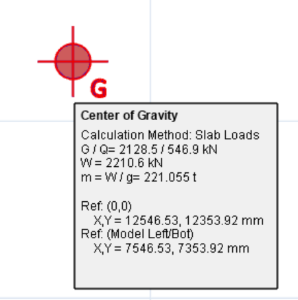
Storey Weight and Center of Gravity Calculations
- The reaction values are calculated at the beam end nodes & regarded as masses at the joints.
- If this option is selected, then masses in the joints are used in center of gravity and weight calculations.
- This option should not be used for flat slab system (no beams), as flat slab loads will be lost in storey weight calculation.
- Hence, this method can be used for both flat slab system as well as beam slab system.
- In short, if there are no beams in the system, like in flat slab, then “Use Undecomposed Loads” option should be used.
- As such, this is the default method, as it can accurately calculate the storey weight for all types of system.
The mass/weight determined for the chosen option can be reviewed by hovering the cursor over the Center of Gravity indicated on the form plan after running a Building Analysis (example below)
Related Articles
Effective Stiffness Modifiers
In ProtaStructure, effective stiffness modifiers of the slabs could be adjusted for different analysis methods. One of the method is using the “Finite Elements Floor Analysis” option independent from the building under vertical load cases only. This ...Flat Slab Modelling, Analysis and Design Guide
This design guide discusses the modeling, analysis and design of flat slab model in detail at here: Flat Slab Training Manual 2026 Flat Slab Training Manual 2022 Users who wish to understand the modeling, analysis and design for flat slab model are ...Diaphragm Modelling Example
In a typical building lateral resistance is provide at a few discrete points and it is assumed that applied lateral loads will be distributed to the lateral load resisting systems via floor diaphragm action. Within ProtaStructure diaphragm modelling ...Raft Foundation and Piled Raft Foundation Analysis & Design Example
Raft Foundation Example This example is based on the "Quick Start Guide Concrete Complete" model which is automatically installed in the default ProtaDataXXXX folder. In this example we will be inserting a raft foundation and then piled raft ...Building Analysis Overview
Having modeled your structure and defined the parameters/loading to be applied, you are now ready to generate the member design forces. These are determined by performing a 3D analysis of the whole building. The pre and post analysis stages, along ...