Cracking and Creep Factor Calculator
Stiffness Factors Introduction
Beam, Slab, Column and Wall stiffness factors can be set automatically to make an allowance for cracking and creep. An automated calculation is provided for this purpose as explained below, Cracking & Creep Calculator
Alternatively the stiffness factors can be defined individually if required for maximum flexibility.

Users are also advised to read through the Effective Stiffness Modifiers Design Guide.
The example given in the design guide would be helpful for explaining the concept to users.
The example given in the design guide would be helpful for explaining the concept to users.
As explained in the above stated article & also this article Modelling, Analysis & Design Flowchart, there are 2 pathway of analysis to obtain members and slab forces :
1. Building Analysis with option to mesh the floor slab.- This can be done by going to the Analysis ribbon > click Building Analysis > Model Options tab > Slab Model tab > check option Include Slabs in Model2. FE Floor Analysis, where floor slabs must be meshed.- This can be done by going to going to Analysis ribbon > click FE Floor Analysis
For the 2nd method, in the FE Floor Analysis dialog, there is a function to estimate the Cracking & Creep factor (as below).
Cracking & Creep Calculator
The "Cracking & Creep" button is used to calculate a stiffness factor which is then applied to the FE model. The purpose of this factor is to make an allowance for creep, cracking and shrinkage when determining an estimate of total long term concrete slab deflection.
Key points to note when considering total long term concrete slab deflection are:
- The total deflection estimate is obtained by reviewing the G+Q*F combination.
- The stiffness factors suggested also take account of the load factors –the deflections displayed are a serviceability estimate.(There is no requirement to make further adjustments to the deflections).
- If you are using the stiffness factor adjustment as suggested then there is absolutely no value in looking at the deflections for G or Q individually. (These results are only left visible to accommodate engineers with their own methods of estimating the deflection based on different adjustment factors.)
- It needs to be understood that creep and cracking effects do not apply equally to dead and imposed loads – this is another reason why the individual G and Q deflection plots should be viewed with extreme caution if at all.
- If the total deflection determined by this method is greater than span/250 then in general the slab may be regarded as being too thin.
- It is Prota’s view that considering deflection in this simple, well established and accepted fashion remains the most pragmatic approach in most situations. (Refer to concrete centre guide “How to design reinforced concrete flat slabs using Finite Element Analysis” for further information.)
- The possibility of adding reinforcement to control deflection is sometimes raised. This requires a more theoretical approach where once again creep cracking and shrinkage must all be considered. Our research indicates that this approach cannot readily prove slab depths which have always been accepted without the addition of reinforcement, are in fact acceptable. You also have to add a lot of reinforcement to make a small % difference to the deflection. Therefore, it seems that indiscriminate use of such an approach may lead to wasteful specification of additional reinforcement.
To calculate the stiffness factor to apply:
- Choose the “Load Type” (either Domestic/Office or Storage).
- Enter the “Average/Typical Dead Load” on the current storey.
- Enter the “Average/Typical Live Load” on the current storey.
- A suggested range for the stiffness factor is calculated based on the above input. This range also depends on the code being designed to.
- The “Stiffness Factor to Apply” is displayed at the bottom of the dialog. The default is the lowest value in the suggested range.
- Click the “OK” button to apply the stiffness factor.
On the Model Preparation page, the Beam, Slab, Column and Wall stiffness factors will now be set to the calculated value.

Stiffness adjustments are in accordance to reference : ‘The Concrete Centre publication ‘How to design reinforced flat slabs using finite element analysis’ by O Brooker, May 2006 (HTFS for short).
- Creep cracking and shrinkage are all factors that affect the long term deflection of concrete.
- Short term E (Est) should be reduced to allow for these factors, a long term value (Elt) should be used in analysis.
- ProtaStructure auto cracking & creep allowance follows the above guidance. The coefficient range suggested effectively convert the factored combination displacement to a serviceability estimate for total long term deflection.
Calculation for Stiffness Factor to Apply
Notation | |
G | Average Typical Dead Load |
Q | Average Typical Live Load |
Cg | Dead Load Factor |
Cq | Live Load Factor |
MCSF | More Conservative Stiffness Factor |
LCSF | Less Conservative Stiffness Factor |
SR_lower | Lower Value of Suggested Range |
SR_upper | Upper Value of Suggested Range |
1) Calculate Load Ratio
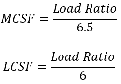
2) Calculate Stiffness Factors
a) Domestic/ Office
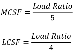
b) Storage
3) Calculate Suggested Range
a) Eurocode and National Annexes
b) Other Codes (British Standard and ACI)
4) Stiffness Factor to Apply
Related Articles
Effective Stiffness Modifiers
In ProtaStructure, effective stiffness modifiers of the slabs could be adjusted for different analysis methods. One of the method is using the “Finite Elements Floor Analysis” option independent from the building under vertical load cases only. This ...FE Analysis of Foundations Overview
The foundation system is modelled in the Graphic Editor and can comprise of mats, piled rafts, pads, pile caps and strip footings. All of these foundation types can be analysed in the FE Raft Foundation Analysis module. Prior to FE Raft Foundation ...Flat Slab Modelling, Analysis and Design Guide
This design guide discusses the modeling, analysis and design of flat slab model in detail at here: Flat Slab Training Manual 2026 Flat Slab Training Manual 2022 Users who wish to understand the modeling, analysis and design for flat slab model are ...Difference between Building Analysis and FE Floor Analysis
This article explains the differences between Building Analysis and FE Floor Analysis & which method is suited for different structural system. The fundamental differences of the analytical model created are shown in the below diagram. For detail ...Model Options
Options to be used in analysis can be specified in “Model Options” page of “Building Analysis” form. “Model Options” comprises of four tab pages namely, Model, Shear Wall Model, Slab Model, and Settings. Any modifications made in this page can be ...