Form Plans
General
Form Plans can be drawn for different scenarios. Unlimited numbers of form plans can be generated with different display options on the same or different drawings.
Dialog is composed of 3 parts:
- Storeys : Select stories to be generated
- Detailing Options : Select the preferred options for each type of detail by highlighting them.
- Common Options : These setting can be found in all "Draw Details" dialogue. The common options allow to insert Sheet (Title block), quantity table, model info and adjust scale of drawing。

For the detailed explanation of common options, kindly refer to Detail Drawing Manager : Common Options.
Navigation
- "Details" treeview context menu > Storeys > Select any storey > Right click > Draw plan view
- Second method is to right click on Form Plans > Draw plan view
- Alternatively uses Detail Drawing Manager > Form Plan
Draw Details - Form Plan
Some of these options (i.e. "Option 3") are able to pre-configure in ProtaStructure > Settings Center > Plan Details > Form Plan & Column Application.
"Options" Tab
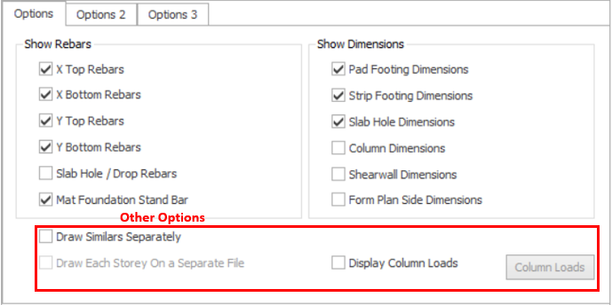
Show Rebar
- X Top Rebars : Generates X direction top rebars if slab strips have been placed in ProtaStructure.
- X Bottom Rebars : Generates X direction bottom rebars if slab strips have been placed in ProtaStructure.
- Y Top Rebars : Generates Y direction top rebars if slab strips have been placed in ProtaStructure.
- Y Bottom Rebars : Generates Y direction bottom rebars if slab strips have been placed in ProtaStructure.
- Slab Hole/Drop Rebars : Generates constructive rebars around slab holes and drops
- Mat Foundation Stand Bar : Generate stand bar details in table for mat foundation.
Show Dimensions
- Pad Footing Dimensions : Generates dimensions for pad footings in foundation storey form plans
- Strip Footing Dimensions : Generates dimensions for strip footings in foundation storey form plans
- Slab Hole Dimensions : Generates dimensions for slab holes
- Column Dimensions : Generates dimensions for columns
- Shearwall Dimensions : Generates dimensions for shearwalls
- Form Plan Side Dimensions : Generates side dimensions for plan view
Other Options
- Draw Similars Separately : When multiple storeys selected, checked this option will allows all of the similar storeys from the selection set are drawn separately. Otherwise, similar storeys are drawn only once as a typical form plan. Similar storey labels are noted in the storey label under the detail.
- Draw Each Storey On a Separate File : To activate this option, "Draw On Separate Files" option must be checked in "Detail Drawing Manager". Checked this option will create form plans on a separate new drawing.
- Display Column Loads : Check this option to show column loads on plan. See "Display Column Loads" section below for more details.
Display Column Loads
Column loads (either at top or at bottom joint) can be shown on form plan drawings for the selected load cases and combinations. Loads include:
- Nodal Loads
- Temperature Loads
- Axial Loads
- Bending Moment
- Shear Force

In order to show/hide the column loads on drawing after generated. You may set the layer of "Column Aux Text" to on/off under "Layers". Please refer to ProtaDetails : Layers for more detail.
"Options 2" Tab
- Print Steel Bar Segment Lengths : The segment length of steel bar (ie. L shape steel bar, the short length and long length) will be printed beside the rebar.
- Print Steel Bar Total Length : The length of steel bar will be printed beside of Bar Label.
- Show Steel Bar Span Lines : This option shows the line of spanning range of slab steel bar.
- Show No. of Bars in Bar Label : This option shows the number of rebars infront of the bar label.
- Print Alternative Layer Information (B1=BB, B2=BT, T1=TT, T2=TB) : This option will change rebar marking from number into alphabet in the back of bar label.
- Dimension Support Steel Bars : This option shows the dimension of support rebars.
- Display Slab Strips : Tick this option to display the slab strip in the Form Plan.
- Draw Steel Members : If this option is checked, plan view will allows to show steel member such as steel column and beam.
- Slab Reverse Deflections : This option allows plan view to show reverse deflections on slab if any.
- Display Pile Numbers : This allows the pile numbers to be shown in plan view.
- Plan View Direction : The plan view direction can be set to "Top" indicates view from top, "Bottom" indicates view from bottom.
"Options 3" Tab
Hatching Options
- Mark Top Most Columns : If this option is checked, the top most column will shows a cross sign indicated column stop here.
- Column Hatch Pattern : Column hatch pattern can be selected from the pulldown list. The hatch will not apply to the top most column if "Mark Top Most Columns" option is checked.
- Column Hatch Scale : Adjust the scale for column hatch pattern.
- Wall Hatch Pattern : Wall hatch pattern can be selected from the pulldown list. The hatch will not apply to the top most wall if "Mark Top Most Columns" option is checked.
- Wall Hatch Scale : Adjust the scale for wall hatch pattern.
Related Articles
ProtaDetails Basic Training Guide
Thank you for choosing ProtaDetails – a revolutionary automated detailing, drawing management & structural component design program that enables you to: Create automatic detail and general arrangement drawings from ProtaStructure models Produce ...Column Application Plans
General Important information of columns such as reinforcement, dimensions, quantity table etc. can be included in Column Application Plans. Dialog is composed of 3 parts: Storeys : Select stories to be generated Detailing Options : Select the ...Layers (ProtaDetails)
General In Layers tab, you can create as many layers as you like. You can use layers to control the colour, line type, line weight and plot style for your geometry (amongst other things) as well as the visibility of all the geometry on that layer. ...Detail Drawing Manager
General Detail Drawing Manager (Draw Details) Dialog is the entry point to generate the detail drawings for selected stories with selected options. Dialog is composed of 4 parts: Storeys : Select stories to be generated Detailing Types : Select the ...Drawing Generation Overview
Steps and basic guideline of generating drawing can be referred to ProtaDetail Basic Training Guide. The best practice is to complete the quick start guide before proceeding to this topic. In these articles will explain on the details of each drawing ...